Build Guide
Visit the official repository to download the example code and get the latest version.
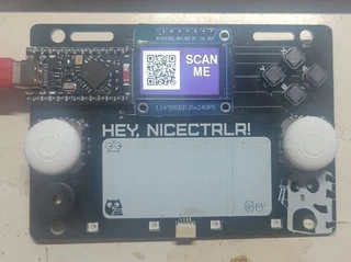
Bill of Materials
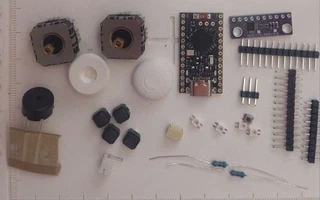
| # | Component | Notes |
|---|---|---|
| 1 | PCB | NiceCtrlr PCB, see hardware/PCB-kicad/ |
| 1 | nice!nano | or compatible nRF52840 microcontroller board |
| 1 | ST7789 display | SPI 1.14" 135×240 px |
| 2 | Analog joystick | FJ08K-S (with or without push button) |
| 4 | 6x6x4.3mm buttons | 6x6x5mm with same footprint also works |
| 1 | ADS1015 | |
| 1 | Passive buzzer | 5.5 mm |
| 4 | RGB LED | SK6812MINI-E (WS2812 compatible), bottom-mount |
| 2 | Pull-up resistor | 3.3-4.7 kΩ axial |
| 1 | Qwiic / StemmQT connector | JST SH 4-pin |
| 1 | Battery connector | JST 2.0 PH 2-pin |
Tools
- Soldering iron + solder
- Flux
- Fine-tip tweezers
- Helping hands or PCB holder
- Isopropyl alcohol + brush (cleanup)
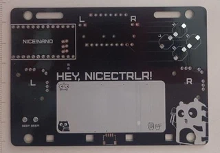
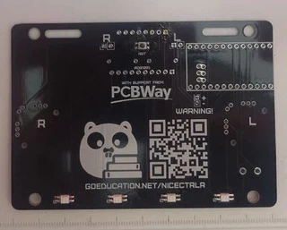
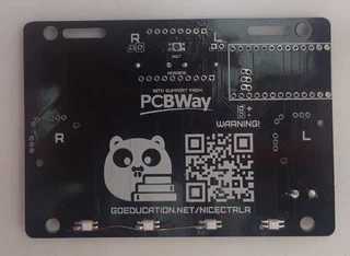
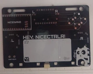
Front
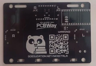
Back
Parts
Assembly Steps
Step 1 - Solder back-side SMD components
Solder the four SK6812MINI-E RGB LEDs on the back of the PCB. The SK6812MINI-E is a bottom-mount LED - the light emits downward through the board cutouts. Check the orientation mark on each LED package before soldering.
Also solder the reset (RST) button. The best strategy is to pre-tin two pads on one side, as pre-tining all four will left your button raised. Then the other two.
Prototype version boards have an error, a severed connection of the last 2 LEDs and need to be connected. The version on this repository has been fixed.
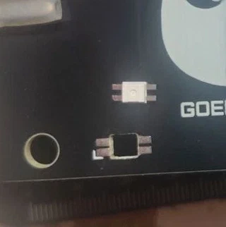
LED orientation detail
Be careful soldering the LEDs, they are oriented. The dented/cut pin needs to be aligned to the footprint with a corner.
Step 2 - Solder the StemmQT connector (front)
Solder the JST SH 4-pin Qwiic / StemmQT connector on the front of the PCB. The connector is surface-mounted; you might use some flux to help you with the process, add some solder to the board, put the connector and push gently with the iron.
Step 3 - Solder the buttons
Solder the four 6x6x4.3mm buttons. Same strategy as with the RST button, pre-tin one side first, put the button, then the other. I recommend doing Y->B->X->A, presolder the middle ground first, as the iron solder has left space room to work between Y-X and B-A.
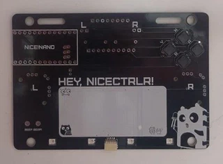
Step 4 - Solder the buzzer and the resistors
Insert the buzzer and the two resistors through the front and solder on the back.
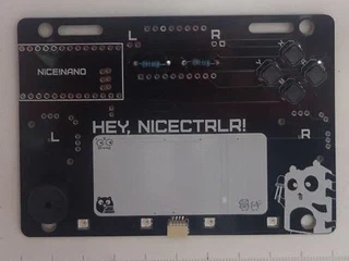
Step 5 - Solder ADFS1015
Insert the ADS1015 module in the back of the board. I used a little trick to put both PCB together so it fits nicer. Watch the following images to get an idea, but instead of ADS1015-header-NiceCtrlr I went by header-ADS1015-NiceCtrlr.
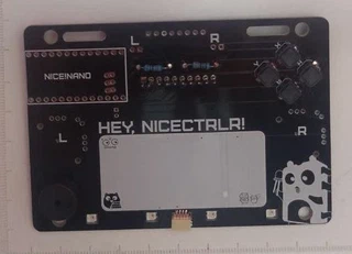
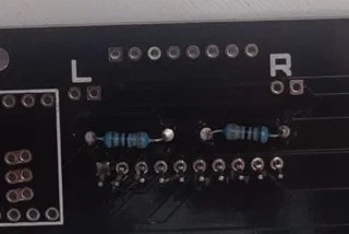
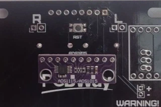
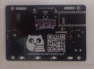
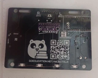
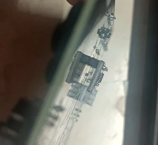
The other option is as you could expect, but it left the module raised.
Step 6 - nice!nano
Insert the three pin header strips for the nice!nano. Keep them perfectly vertical - use the nice!nano itself as a alignment guide without soldering it yet.
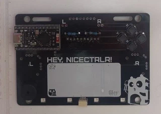
Press the nice!nano onto the pin headers. The USB-C port should face the left edge of the badge. Solder the nice!nano to the headers.
Optionally place a strip of kapton tape over the nice!nano to hold it in place while soldering on the back side. Solder everything on the back side.
Step 7 - Display
The ST7789 display already comes with the headers soldered (most probably), so it’s easier. Do it as with the nice!nano.
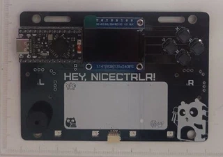
Step 8 - FJ08K-S joysticks
Finally solder the two joysticks and put the plastic caps.
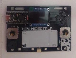
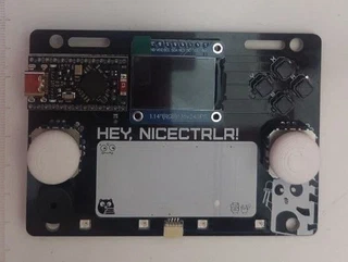
Step 9 - Trim excess
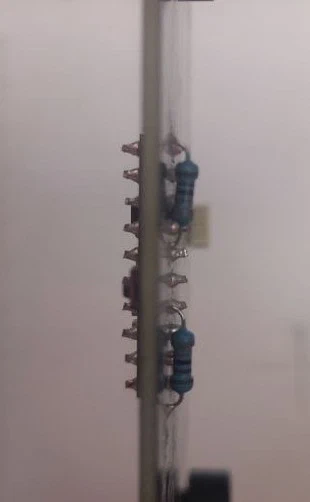
Everything is solder now, use some plipers to cut excess of the headers on both sides.
Step 10 - Flash the firmware and test
Connect the badge to your computer via USB-C and flash the demo firmware:
cd tutorial
tinygo flash -target nicenano ./basics/step0
Done
Your NiceCtrlr is ready. Here’s where to go next:
- Tutorials - step-by-step TinyGo programming guide
- Examples - standalone, feature-complete programs
- Configurator - customize your badge online