XIAO
Visit the official repository to download the example code and get the latest version.
What if your development board just wasn’t big enough? This is a fully functional, 15× scale replica of the Seeed Studio XIAO ESP32-C3 — 3D printed, wired up, and ready to actually run TinyGo.
Yes, it’s a giant board built to run code meant for a board the size of your thumbnail. The irony is intentional.
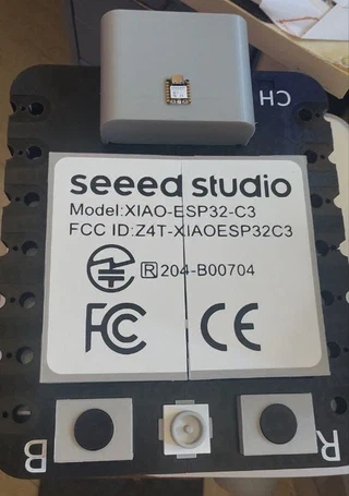
The original vs the replica. The real XIAO weighs about 5 grams and fits on a fingernail. Its giant twin takes up half a desk.
The concept
The Seeed Studio XIAO ESP32-C3 is one of the smallest and most capable microcontroller boards available — roughly 21 × 17.5 mm, with a USB-C port, WiFi/BLE, and a full set of GPIO pins. It’s one of the go-to boards for TinyGo, the Go compiler that targets microcontrollers.
The goal was to build something that works as a conversation starter, a teaching prop, and a practical tool all at once.
The result is a giant XIAO that:
- Is electrically functional — all pins are wired through to a real XIAO hidden inside
- Has a swappable chip housing (the top gray block, held by screws) to adapt the form factor for different tasks
- Has a swappable interior (held by magnets) so the inside can be reconfigured — for example, as a compact component organizer for workshop sessions
- Has a giant USB-C port that actually accepts a real USB-C cable to power and program the hidden XIAO
Part 1: The 3D printed parts
The board is split into several distinct printed pieces to fit most common 3D printer beds (20×20 cm). It has slots for joints, and the screws from the chip housing (the big gray box) help hold everything together.
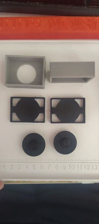
Two button frames, and the round caps for the BOOT and RESET buttons.
The main board frame is printed in black and assembled in sections. The chip housing on top and the USB-C connector shell are printed in gray to match the original XIAO’s color scheme. The buttons — BOOT and RESET — are separate two-part pieces: a square frame and a round cap, just like the originals.
Everything is printed without supports where possible to keep the surfaces clean. The tolerances are tight enough that the buttons feel satisfying to press.
Part 2: Wiring the pins — copper tape as a conductor
Here’s the key technical trick: the 14 GPIO pads (plus GND, 3V3, VUSB, BAT, and the debug pads) are reproduced as conductive copper tape patches wrapped around 3D printed pin stubs on the edges of the board.
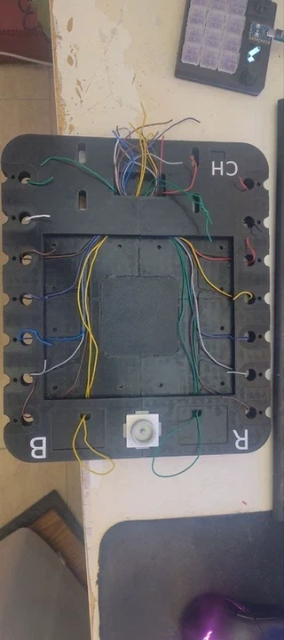
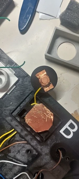
Wiring and applying copper tape. Each pad becomes its own solderable contact.
Each stub has copper tape folded over and pressed into the cavity, creating a continuous conductive surface. A wire is then soldered to each pad and routed through the board’s internal channels to the real XIAO.
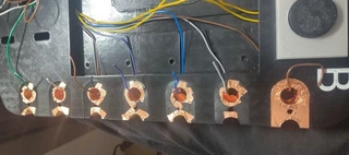
Every pin gets its own copper-tape pad and soldered wire. There are 14 GPIO pins plus power, ground, and the debug pads — 22 connections in total.
The back face of the board reproduces the original XIAO labels — D0 through D9, BAT+/−, 3V3, VUSB, GND, and the JTAG debug pads — all silk-screened as part of the 3D print itself. The battery pads and JTAG pads are printed for looks but intentionally left non-functional for safety.
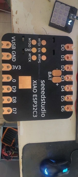
An exact reproduction of the XIAO pinout, at 15× scale. If you know the original pinout, you know this one.
The internal wire routing fills the channels between the pin stubs and converges toward the USB-C cavity at the bottom, where all the connections eventually reach the real XIAO.
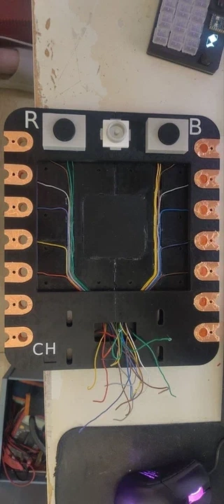
The wiring harness inside the board. Each color corresponds to a specific pin. Routing wires in a 3D printed cavity is its own puzzle.
Part 3: The brain inside the USB-C port
The real XIAO ESP32-C3 lives inside the giant USB-C connector housing, hidden at the bottom of the board.
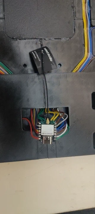
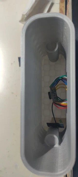
The tiny brain of the whole build. The real XIAO fits snugly inside the giant USB-C housing, with every one of its pads wired to the corresponding giant pad above.
The giant USB-C port cover is magnetically attached and has a small hole to pass a regular (not giant) USB-C cable through — so you can plug it in without breaking the illusion.
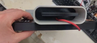
A real USB-C cable plugged into the giant port reaches the XIAO’s actual USB-C connector.
Part 4: The swappable chip housing
The gray block on top represents the ESP32-C3 chip package. It attaches to the main board with screws, making it easy to swap for a different housing designed for a different use case. It’s designed as a double-door box for modularity, but a single-door design or a different internal layout would work just as well.
The interior of the housing is also swappable — held in place by magnets — so the inside can be completely replaced without disassembling the board. Note: N52 neodymium magnets held the interior in place, but not as strongly as expected — worth over-specifying magnet strength if you build your own.
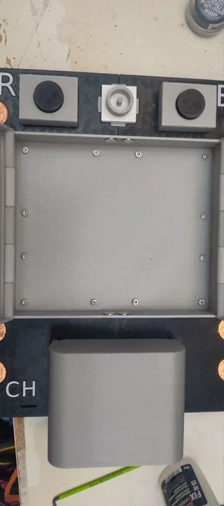
The chip housing opened.
For workshops and hacksessions, the interior can be configured as a component organizer tray: round wells for small boxes of the XIAO ESP32-C3, and velcro ties for bundled cables. Everything a participant needs in a single package.
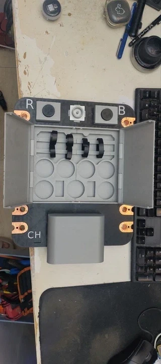
The organizer tray in place. The circular wells hold component tins or small modules; the top rails keep jumper cables bundled and accessible.
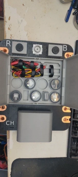
Loaded up for a workshop. Everything a participant needs for a hands-on embedded session, organized inside a giant microcontroller.
The front detail
The front of the chip box reproduces the original XIAO’s regulatory label — seeed studio / Model: XIAO-ESP32-C3 / FCC ID: Z4T-XIAOESP32C3 / FCC / CE — printed multi-color, exactly as on the original board, just 15× larger.
Bill of materials
- Standard PLA filament (black + gray, to match the original XIAO color scheme)
- Copper tape (available at any craft or electronics store)
- Enameled wire, or any thin stranded wire
- A real Seeed Studio XIAO ESP32-C3
- M3 screws and heat-set inserts, for the chip housing
- A handful of N52 neodymium magnets, for the swappable interior
Files
The printable model lives in this folder: xiao_parts.STL.
Once assembled, flash it with TinyGo like any other XIAO — the giant size changes nothing about how you program it. See the examples folder for firmware to try on it.