Rotary encoder
Visit the official repository to download the example code and get the latest version.
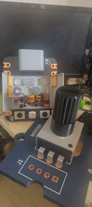
A 15× scale replica of the Grove Rotary Angle Sensor from the Seeed Studio TinyGo XIAO Starter Kit: 3D printed, wired up, and built around a real potentiometer hidden inside the knob.

The finished sensor. Twist the giant knob, and it turns a real potentiometer underneath.
The concept
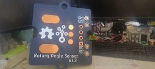
The Grove rotary angle sensor is a simple 3-pin analog input: a potentiometer in a small plastic housing, wired to GND, VCC, and SIG (the Grove connector reserves a fourth pin, NC, not connected). It’s the kind of first component people wire up when they’re learning what an ADC reading even means.
The giant version keeps that lesson intact at 15× scale: a real, tiny linear potentiometer (B10K) sits soldered inside the knob, and its three legs are routed out to giant, solderable copper-tape pads on the base plate, laid out in the same GND / VCC / NC / SIG order as the original Grove connector.
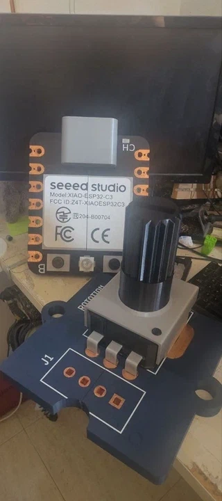
Next to its giant XIAO sibling. Same 15× scale, same idea: real components, giant terminals.
Step 1: the base plate
The base plate is split into four printed quadrants (so it fits on a normal 3D printer bed, one big enough won’t need the split at all). Each quadrant locks into its neighbors with a notch, and a small separate key piece bridges the seam and keeps the joint from flexing.
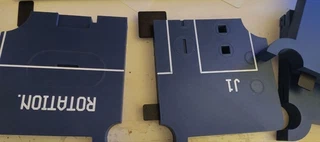
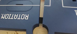
Each seam gets its own key piece, glued in with cyanoacrylate (CA) glue.
Glue every seam and every key piece with CA glue, then let the four quadrants cure into one solid plate.
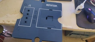
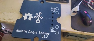
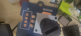
The finished plate, front and back. The square cutout in the middle is where the potentiometer body will sit.
Step 2: centering collar
A small printed collar glues into the central cutout, between the base plate and the potentiometer body. Its only job is to center the body so it sits flush and square once it’s glued down in step 4.
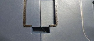
Step 3: wiring
Four wires need to run from the potentiometer, through the collar, down through the base plate, and out to the back pads. The base plate has a small hole for each wire.
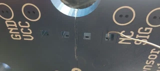
Thread the wires through from the front. A pair of tweezers or fine pliers helps push them through the tight holes. Leave the wires noticeably longer than you think you’ll need: it’s much easier to trim excess later than to redo a wire that turned out too short.
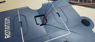
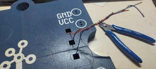
Step 4: gluing the potentiometer body
With the wires routed, glue the potentiometer body onto the base plate, over the centering collar from step 2.
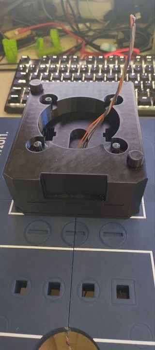
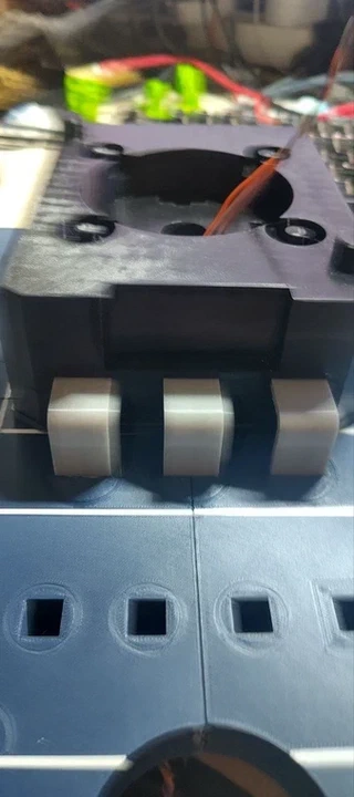
Step 5: decorative pins
Three small pins glue onto the front edge of the body, echoing the three exposed legs of the original Grove sensor’s potentiometer.
Step 6: bearing wells (optional)
The body has four wells sized for standard 608 bearings (skateboard bearings), meant to help the knob spin smoothly. In practice they turned out not to be fully necessary: the potentiometer’s own shaft holds up the knob fine on its own. Consider this step optional.
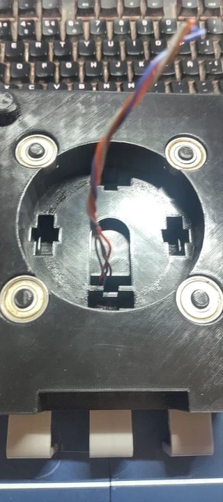
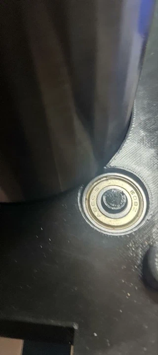
Step 7: soldering the real potentiometer
Solder the real potentiometer (a linear B10K) into the slot in the middle of the body, one wire per leg. Once it’s soldered in, gently pull on each wire from the back of the base plate to take up the slack left in step 3 and get the length just right.
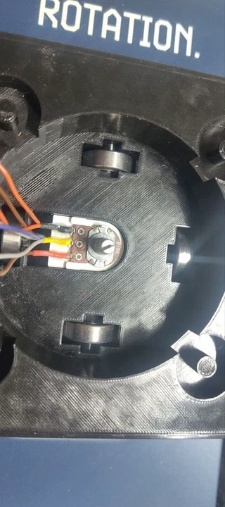
Step 8: copper tape pads
The last step is turning the wire ends into solderable, touchable pads on the back of the base plate, the same way the giant XIAO’s pins work: copper tape pressed into each shallow pad recess.
Strip each wire and route it into the outermost hole of its pad (the SIG, GND, and VCC pads all carry a wire; NC doesn’t need one, since it isn’t connected on the real sensor either). Make sure the bare wire touches the copper once the tape goes down.
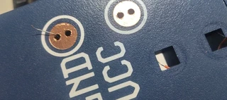
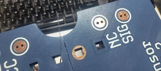
Cutting clean circles and squares out of copper tape by hand is fiddly: a cutting plotter (a Silhouette or similar craft vinyl cutter) makes much cleaner pads than scissors, and it’s worth the patience to set up the cut file correctly before committing the tape.
The result
Bill of materials
- Standard PLA filament (blue for the base plate, gray and black for the body and knob)
- Cyanoacrylate (CA) glue
- Copper tape
- Stranded wire, four colors
- A linear potentiometer, B10K (10 kΩ)
- Four 608 bearings (ABEC5 or similar), optional
- A cutting plotter (Silhouette or similar), optional but recommended for the copper pads
Files
The printable parts live in this folder: groove_rotary_angle.STL, or split into four separate print jobs as groove_rotary_angle_1.3mf through groove_rotary_angle_4.3mf (with groove_rotary_angle.3mf as the combined project file, and groove_rotary_angle.DXF for the flat profile).
Once wired up, it reads just like the real Grove rotary sensor: GND and VCC to power, SIG to an ADC pin. See examples/rotary for TinyGo firmware that reads it and drives a WS2812 strip with the result.